Simple operation – safe and reliable control
Simple operation – safe and reliable control
DST control pendants
DST control pendants
Safely control simply everything
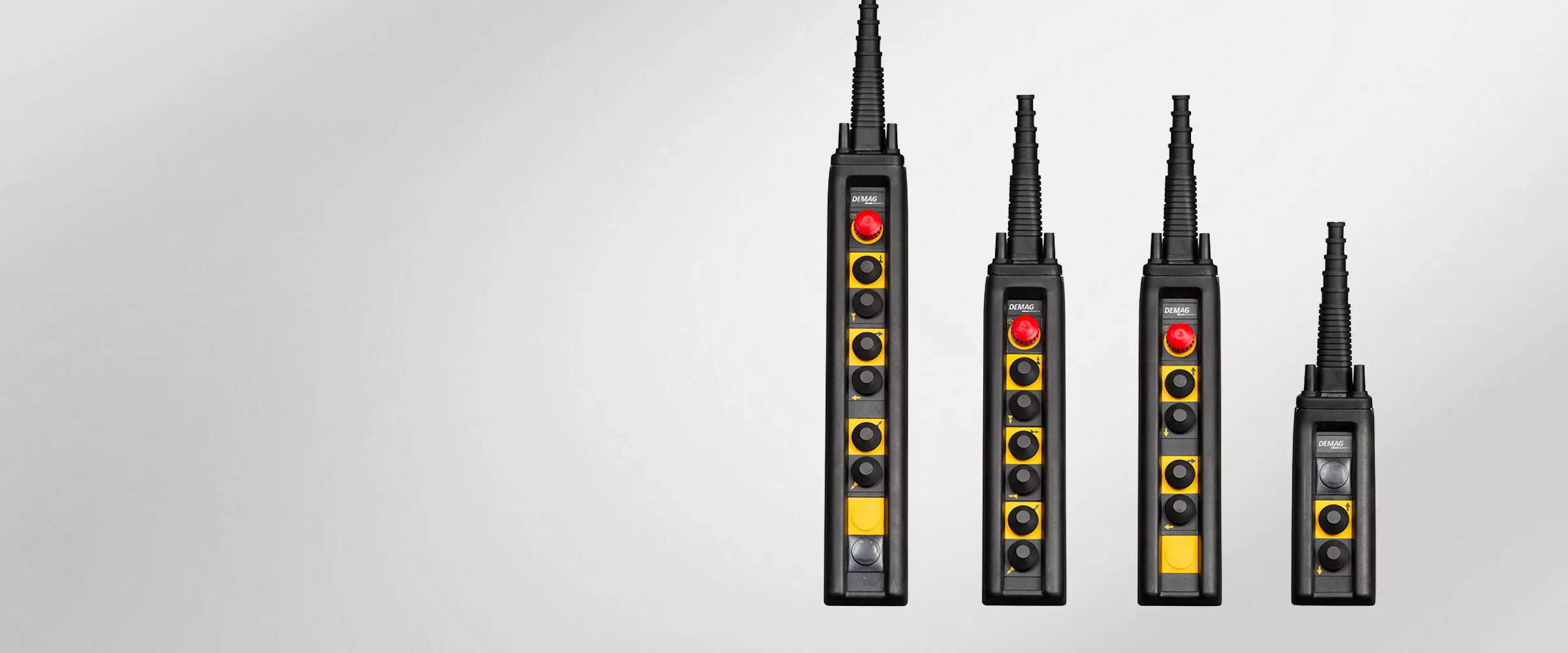
DST control pendants are real universal solutions – for universal operation of cranes, hoists and machinery. Their benefits are evident:
- Three sizes with multiple combinations of operating and switching elements
- Ergonomic design and operation
- Switching elements for direct and contactor control
- High switching capacity
- High operating reliability.
Your Contact

Sachin Pange
Sachin Pange
Aker Solutions Building. Level 3, Survey no. 75/2/3, Baner, Pune, 411045 Pune, Maharashtra, India
Phone:
9673330297
Email:
Further information
The benefits at a glance
Individual configuration
- User-friendly design in various configurations with 3, 6, 7 or 9 operating elements
- Individual configuration and combination of two DST pendants for up to 18 openings
Convenient operation
- Fatigue-free operation thanks to ergonomic housing design
- Sloping control pendant design permits operators to work in a natural, comfortable posture
High safety and reliability
- High operating reliability thanks to additional strain relief elements
Technical data
DST series control pendants offer the following outstanding technical details:
- Permissible ambient temperatures for rubber and thermoplastic parts -25°C to +70°C, housing -40°C to +150°C
Control
- 3, 7 or 9 openings in a single row (also for special inserts)
- Two DST 6, 7 or 9 pendants can be combined for up to 18 openings (in two rows)
- Switching elements for single-stage, two-stage or variable control
- Simultaneous 2-pole switching for direct control
Housing
- Enclosure made of glass fibre-reinforced polyester with high resistance to impacts
- Flame-resistant and self-extinguishing
- Highly resistant to spirits, ether, petrol, turpentine, benzene, grease, oil, dilute acids or alkaline solutions.
Safety
- Switching distances and forces to DIN 33401, holding force < 8 N
- Positive opening of interlocking contacts in the switching elements
- Movements in opposite directions cannot be simultaneously actuated
- Protective insulation to VDE 0100 Part 410
- IP 65 enclosure to DIN VDE 0470/EN 60529/IEC 529
| Main current switching elements | ||||||
|---|---|---|---|---|---|---|
| Type | SES 1 Z | SES 2 Z | SEDN | |||
| Type | Single-stage switching element 2 NC + 2 NO | Two-stage switching element 2 NC + 2 NO in the 1st stage 2 changeover contacts in the 2nd stage | Single-stage crane switch (emergency stop), 3 NC | |||
| Utilisation category to VDE 0660/ EN 60947 | AC 3 / AC 4 | AC 3 / AC 4 | AC 1 | |||
| Control current switching elements | ||||||
| Type | SES 1 | SES 2 | SESN | |||
| Type | Single-stage switching element 1 NC + 1 NO | Two-stage switching element 1 NC + 1 NO in the 1st stage 1 NO in the 2nd stage | Single-stage switching element (emergency stop), 1 NC + 1 NO | |||
| Utilisation category to VDE 0660/ EN 60947 | AC 15 | AC 15 | ||||
| (Main current) and control current switching elements | ||||||
| Rated operating voltage [V] | 230 | 400 | 500 | 230 | 400 | 500 |
| Rated operating current [A] | 10 (20) | 6 (12) | 4.5 (9) | Ith 2 | 25 | (for breaking capacity up to 5.5 kW) |
| Nominal insulation voltage | Ui 500 V~ to VDE 0110, CSA 150Vac |


